Light Language (evolution of sheep)

Abstract:
The plan is to represent a living language with gesture from the body in a physical space. A visualization will take the form of luminosity.
A group of self-aware objects will communicate a physical presence between each other, referencing a visual understanding of the boundaries of proximity inherent in wireless communication.
How does this work?
Part 1

A glowing object (ball) is placed on the ground. Let say this ball is blue. Blue will present one kind of language. When the ball is picked up it fluctuates in luminosity. (Ground level being dim, waist level being max brightness, and overhead being dim again) This experience indicate an evolution of language threw a variant altitude of brightness. Computationally the ball is aware of is altitude and will translate this data into luminosity.

Time sequence overlay
Part 2
There are two glowing balls each ball will have the attributes I speak of in part 1, along with a proximity awareness. Each ball will be different colors (for this example blue and red). The balls will be looking for each other. When in range or sight of the other, the balls will assume the others color luminosity in conjunction with its own.
The visualization or physicalization of this experience will be a blue object gathering red light and turning from blue to purple and a red object gathering blue light, turning from red to purple.

In this visual we see the influence of red in the blue and the influence of blue in the red.

This image shows two people, one with a red ball and other with a blue one. The balls are out side of the range to influence one another.

At this point each ball is gathering each other’s luminosity.

This image shows a particular geographical locations were both people and balls share the same illumines color. This purple represents influential equality.

We can refer to the purple as the creation of a new language. The evolution or hybidization of english and spanish., this new language being a Pachuco of sorts, part of both the blue and red languages.
Looking at Nature.

The above reads: Trevor, there are many phosphorescent creatures in seawater. I've gone scuba diving on a moonless night and we played like wizards in Fantasia throwing fireballs as we moved when the dive lights were off.
This image refects on my process of finding a place the porject may live.

Sheep on a bike at night riding over a hill.
Step 1
In clarifying these ideas, I had some preliminary discussions with a few people about what technologies could help realize this project. I then turned to the natural world that surrounds us for inspiration. I asked my self what existed out there in our day to day lives that touches on these ideas? My conclusion was some one riding a bike at night, a whale, and a TV receiver.
 I found this child’s drawing to be quite fascinating. Look at how he/she fills in the moon as black to represent night.

I looked at many different light sources for bikes. This reminds me of those lights you see under cars cursing on some Florida strip at night.

These image metaphors all the parts on this banana seat bike with the hardware I am looking at realizing this project with.

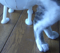
Here is a cat sitting in the pathway of a infrared LED. The receiver gets a image of the head.

Whales use biosonar to understand there seroundings.

The above reads: The red line represents the telemetry of the light language in flight.
Useful definitions of telemetry :
-Wireless remote monitoring and control of a process or device.
-Transmission and collection of data obtained by sensing conditions in a realtime environment.
-Automatic transmission and measurement of data from remote sources by wire or radio or other means
Prototype
The design goals started with a few important guild lines:
- The object needs to be easy held in you hands.
- It must be light enough for a small child to pick up.
- The structure has to transmit even luminous color. (No hot spots).
- All the working hardware must be contained inside the structure.
- The object must have enough structural integrate to withstand being picked up on a continual bases with out compromising its form.
- Each object should have an embedded power source (the power supplies should be good for at least 2 hours.
- Keep cost as low as possible, with a careful consideration of time spent constructing the prototypes.
- There needs to a minim of 2 independent objects.

fuzzy light emitting bunny
view image
After consider these guild lines, the next step was gathering the piece to initiate process. Here is a general list of the main components.
- Two microprocessors (Parallax BS2)
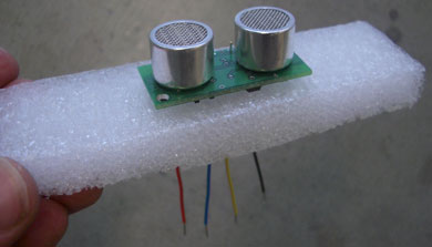
- Two ultra sonic range finders
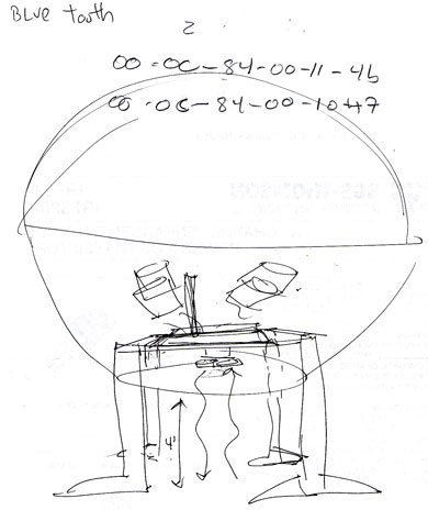
- Two Bluetooth modules (at first I was looking at using a series of Infra red LEDS and a remote receiver, but it turned out the Bluetooth was a better options)
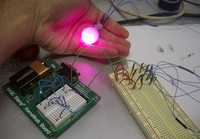
- 16 red super bright LEDs
- 16 blue super bright LEDs
- 2-10 inch hamster ball
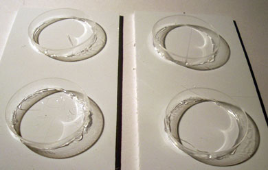
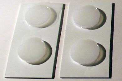
- Silicone.
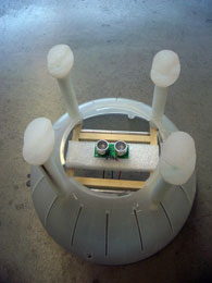
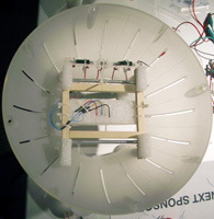
The inner workings.
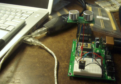
When planning to create objects that are self aware of there relative distance to the ground. I turned to microcontroller for the main source of intelligents. In this case I aimed an ultra sonic range finder towards the ground. Ultra sound is sent in a series of pulses, which reflect from the grounds surface and are collected again by the range finger. Now when the object is picked up and moved it senses relative distance to the ground in real-time, I think of this as being altitude aware. The microcontroller now uses this sensor information or a data stream to convert it to brightness.
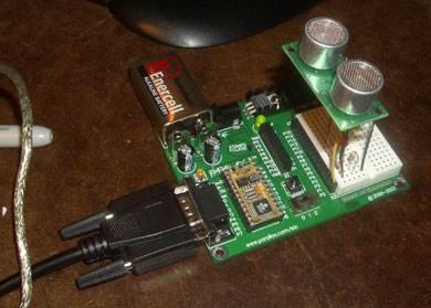
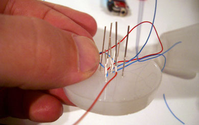
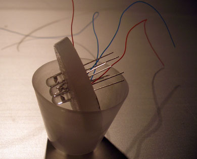
This image details the microcontroller and ultra sonic range finder
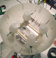
The relative brightness comes from a series of LEDs. The LEDs can be referred to as the actuators. Lets say this particular object has red LEDs. Now the object has an intelligence to alter its brightness in relation to its relative altitude. The microcontroller is programmed with a rule set (behaviors), and will make decisions based on a particular attitude. In this case when the object reaches around waist height (1 meter) it will be a maximum brightness. As you move the object overhead it will appear dim again. To control the apparent brightness we use PWM (Pulse Width Modulation) to shift the proportion “on” time and ‘off’ time of the LED.
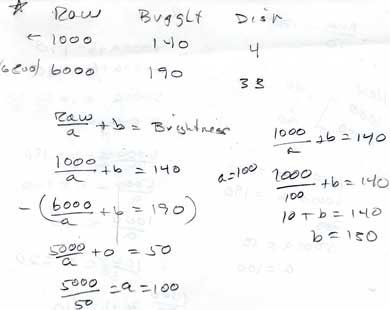
This math show the formula used to alter brightness in relation to its relative altitude.
Now lets talk about how these objects translate this luminous information in forms of relative communication to one another. Each object has Bluetooth modules embedded in them; this allows for a certain range they can pass data information (the brightness and color). When the objects are in proximity to each other they will pass each others relative data stream. Lets say our second object has blue LEDs. This blue object will pass its relative brightness to the red object creating shades of purple. The red object will do the same by passing its red information to the blue one. In each object there are two sets of LEDS a blue set and a red set. One color set is considered dormant until the Bluetooth detects the other object. At this point the dormant set becomes active, creating active shades of purple. One way I like think about this idea is you have control over half of your object as well as control over half the other one, relative communication.
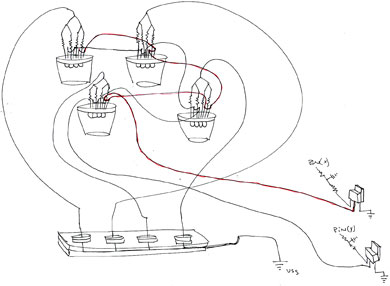
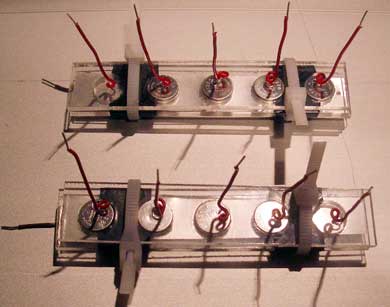
Schematic sketch of 16 LEDs powered by a series of 3-volt lithium batteries
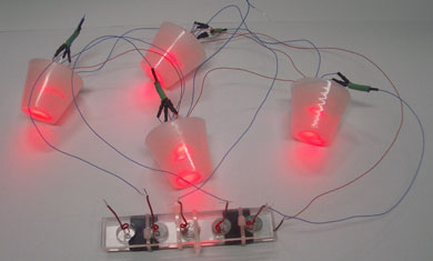
red active blue dormant
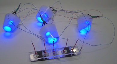
blue active red dormant
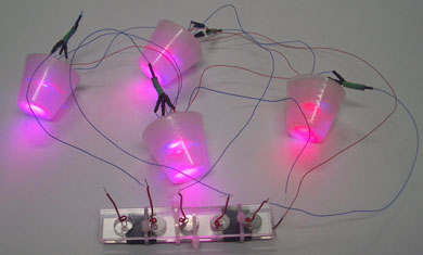
red and blue active
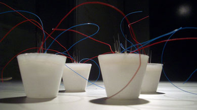
a study in blending and
diffusion
of red and blue light to create purple.
Trouble Shooting
Debugging an ultrasonic range finder in relation to PWM (Pulse Width Modulation) of a LED.
The problem:
Inconsistency in light behavior, flashing on and off, erratic jumps in light intensity.
The solutions:
Software: Looking at a model of hysteresis we averaged 3 consecutive distance reading to reduce the inconsistence in light behavior (jumpiness). [this is called a running average]
Hardware: Added a N-FET transistor (IRF520, Jameco part # 209226) [npn field effect]
1. The N-FET allowed us to switch a number of high current LED’s. We were using the PWM (Pulse Width Modulation) to shift the proportion “on” time and ‘off’ time of the led. This controlled its apparent brightness. [this proportion is usually called the “duty cycle]
2. The problem is the sonic sensor has a slow response time.
3. This interprets the PWM command for to long of a time
4. When the PWM command is not running it converts the pin it’s using to an input pin. Input pins don’t suck a lot of electricity (they sink only a few nano-amps of current), but they don’t source any either. This turns off the LED while the sonic rangefinder is taking a reading.
5. The gate of the N-FET (a small capacitor) holds enough current to keep the transistor on while the PWM is not running, avoiding the intermittent LED illumination.
6. The N-FET is usually used because it’s a good switch for high currents.
7. A better solution was found by using the PWM instruction to power a simple D to A (digital to analog) converter. This was a combo of a 15K resistor and a 0.47uF capacitor. The capacitor acts as our storage system, and converts the PWM digital pulse widths to an analog voltage.
8. This then proportionally turns on the transistor, which controls LED brightness. The LED stays on during the range finding operation because the N-FET and pin input state provide negligible current drain on the 0.47 uF capacitor.
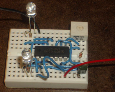
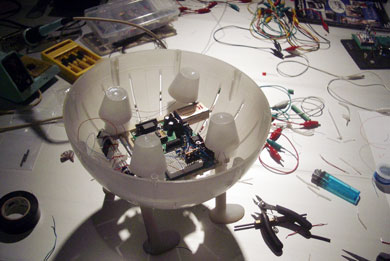
Detail of inferred LEDs on prototyping board; the IR are replaced with Bluetooth modules.
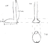
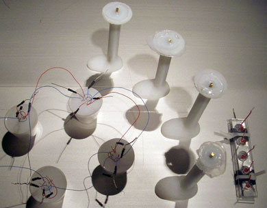
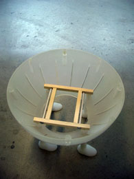
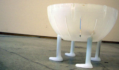
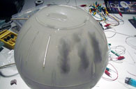
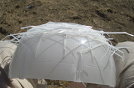
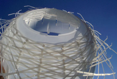
Structure development (evolution of a sheep)
A quick sketch of the structure